
Published On Mar 28, 2023
Please Donate:
BTC:384FUkevJsceKXQFnUpKtdRiNAHtRTn7SD
ETH: 0x20ac0fc9e6c1f1d0e15f20e9fb09fdadd1f2f5cd
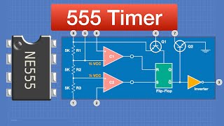
0:00 NE555 - The Complete Guide
0:56 The 5k resistor divider in the NE555.
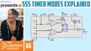
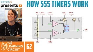
2:05 The input stage of NE555. How does a comparator work?
3:17 Use of comparators in the NE555.
4:14 How does the RS flip-flop work?
5:15 The switching principle of the RS flip-flop in the NE555.
6:41 NE555 output stage. The invertor and the transistor switch.
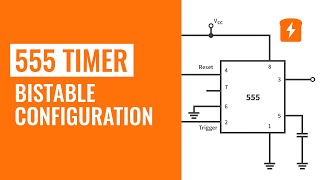
8:27 BISTABLE MODE using the Trig and Tresh inputs.
11:07 Bistable mode using the Reset input.
11:44 Notes on pull-up and pull-down resistors usage.
11:55 Bistable mode with Trig and Thresh tied together.
14:28 MONOSTABLE MODE.
17:30 Delay timer using the monostable mode.
18:16 Formulas for delay calculation.
19:42 The CONT (control) pin in the NE555.
20:35 One-shot multivibrator, sample implementation.
21:21 ASTABLE MODE (the oscillator).
23:52 Controlling Duty cycle in the Astable mode.
24:44 Two-diode connection scheme of the NE555.
26:21 Discharging the capacitor using pin 3 of the NE555.
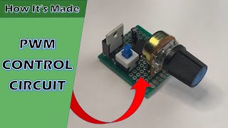
26:57 NE555-based PWM-controller.
27:59 Parasite oscillation in the 555.
29:19 How to make frequency stable as duty cycle changes?
30:41 Using the CONT pin to fine-tune the comparator operation.
32:02 PWM-controller for high current load using a Mosfet.
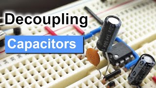
32:52 Why do we need two capacitors in parallel to the supply?
34:12 The CMOS-version of the 555- LMC555
35:29 Ron Mattino -- Thanks for watching!