Published On Jun 23, 2023
Se ti interessa guardare il nostro video in lingua italiana clicca questo link:
• Come leggere un DISEGNO TECNICO INDUS...
• Find out more about our project:
https://www.jaescompany.com/elearning...
• Here are some products installed by our technicians:
https://www.jaescompany.com/catalogo_...
JAES is a company specialized in the maintenance of industrial plants with a customer support at 360 degrees, from the technical advice to maintenance, until final delivery of the industrial spare parts.
Linkedin: / jaes-srl
Facebook: / jaescompany
0:00 ENGINEERING DRAWING
0:50 projections
0:59 isometric axonometry
1:18 multiview orthographic projections
1:32 title block
2:06 scale
3:13 first-angle and third-angle projection
4:32 tolerance
5:21 fillets and chamfers
5:34 AISI and SAE
5:53 types of lines
6:26 section
6:50 detail
7:02 dimension
7:44 threaded holes
8:22 countersink and counterbore
8:34 surface roughness
8:45 notes
8:51 follow JAEScompany
In engineering, when an object is designed, a technical drawing is used to represent it graphically on a screen or sheet, so that engineers, workers, but also those who will need that product, can communicate with each other and understand what it looks like.
In this video we will look at the basics of learning how to read a technical drawing. So that in just a few minutes you can correctly interpret the various elements of it.
There are various regulations that define guidelines for producing technical drawings, such as the international ISO system, but in this video we will only look at the basic principles that are generally common to each standard.
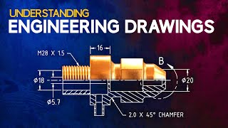
Let's take a very simple object, this shaft has many features, let's look at its Engineering Drawing.
In order to represent the object on a sheet of paper, some of its projections are required, in other words, graphic representations that describe the object.
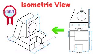
As it can be seen, there is its three-dimensional representation, an aid (not always present) for immediately understanding the shape of the object. The projection is in isometric axonometry, meaning that the xyz axes form 3 equal angles of 120°.
Then we have the multiview orthographic projections, to understand the shape of this object we need three of them.
In essence, there are up to six two-dimensional images representing perpendicular views of the object.
But the first thing to do, to understand orthogonal projections, is to read the title block, a table (usually in the lower right corner) in which all the primary information is enclosed.
It usually includes:
- the company logo and the designer's name (to know who to contact)
- a title, code or drawing number, and anything else needed to identify the object and track it down
- (usually in a separate cartouche), the revision number and date (to tell if it is the latest version of the drawing, and when it was made)
- then there are, the scale of the drawing, and the paper size it needs to be printed on to get the correct scale. These two pieces of information are related: the drawing of an object most times doesn't have actual dimensions, but they are scaled to fit into the dimensions of a sheet, if the sheet is printed in the indicated format then the scale will be correct; in this case the scale is 1to1, it means that actually the drawing is in "full scale" and has the same dimensions as the real object, (so if we take measurements directly from the sheet by means of a ruler, these will be effective) while if it is written for example scale 1to2 , it means that the object is drawn reduced by half of the real size (in practice the dimensions we measure will have to be multiplied by 2 to understand how big it really is) , on the other hand, if it is written 2to1 we are dealing with an enlargement, (the object would be drawn twice as large as it really is, so we have to divide the measured measurements by 2)
- another fundamental thing is the symbol to define whether the orthogonal projection used, is of the first-angle Projection (the European projection) or the third-angle Projection (the American projection).
The orthogonal projections are not randomly arranged; they are aligned with each other by one of these two standards.
With the first-angle Projection, the object lies between the observer and the projection planes; by imagining a cube surrounding the object, each view is projected onto the inner walls of the cube, which is then "unfolded" in order to create all views. For simplicity, it is like laying the object on the paper, and rolling it to arrange the various views.
In contrast, with the third-angle Projection, it is the projection planes that are between the observer and the object; imagining the cube surrounding the object, each view is projected onto the outer walls of the cube to then be "unfolded." For simplicity: starting from the front view, we have its right view, top view above, bottom view below, etc..